Thursday, March 8, 2012

HDD Crash = Pause in posts.

My HDD crashed many weeks back,and its still not back from the Seagate guys,which is why things have stagnated around here.

Hope it comes soon.Expect posts on:
1.SD Card Interfacing with PSoC3/5.
2.Some breakouts I made for specific devices(4Wire Touch,MicroSD and some TI Temperature sensors)
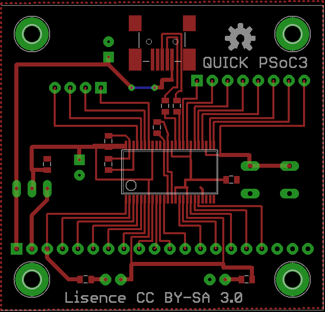
3.New,and easy to home etch PCB layout for the QuickPSoC3. Here.

4.SD Card based bootloader for PSoC3/5.(Read the program from an SD card connected on power-on,then burn & run it.)
5.FreeRTOS on PSoC5,and then maybe port Contiki too?.
6.NXP LPC 1114 Exploration and tutorial series.
7.SPI,I2C for the 89V51RD2.Maybe a 1Wire library too?
8.Python/MATLAB Script for writing to SPI EEPROMs.
9.Interfacing the CYRF6936 based wireless modules with any MCU/embedded target,i.e hardware independent drivers.
10.Wireless Bootloader?
11.An algo for dynamic Node Realization and Intercommunication in decentralized Wireless systems..
12.Generic USB HID based datalogger,PSoC3 powered.
13. A webserver development board,based on the ENC28J60 and the PSoC3


Thats the rough plan of posts and projects after I get my harddisk back.

Tuesday, January 17, 2012

EzPSoC3 - Pictures


Here are a few pictures of the EzPSoC3 board:


Click to view them full size on Picasa Web Albums.

Sunday, January 15, 2012

PSoC3 Hardware - Quick and Dirty - Fab & Testing

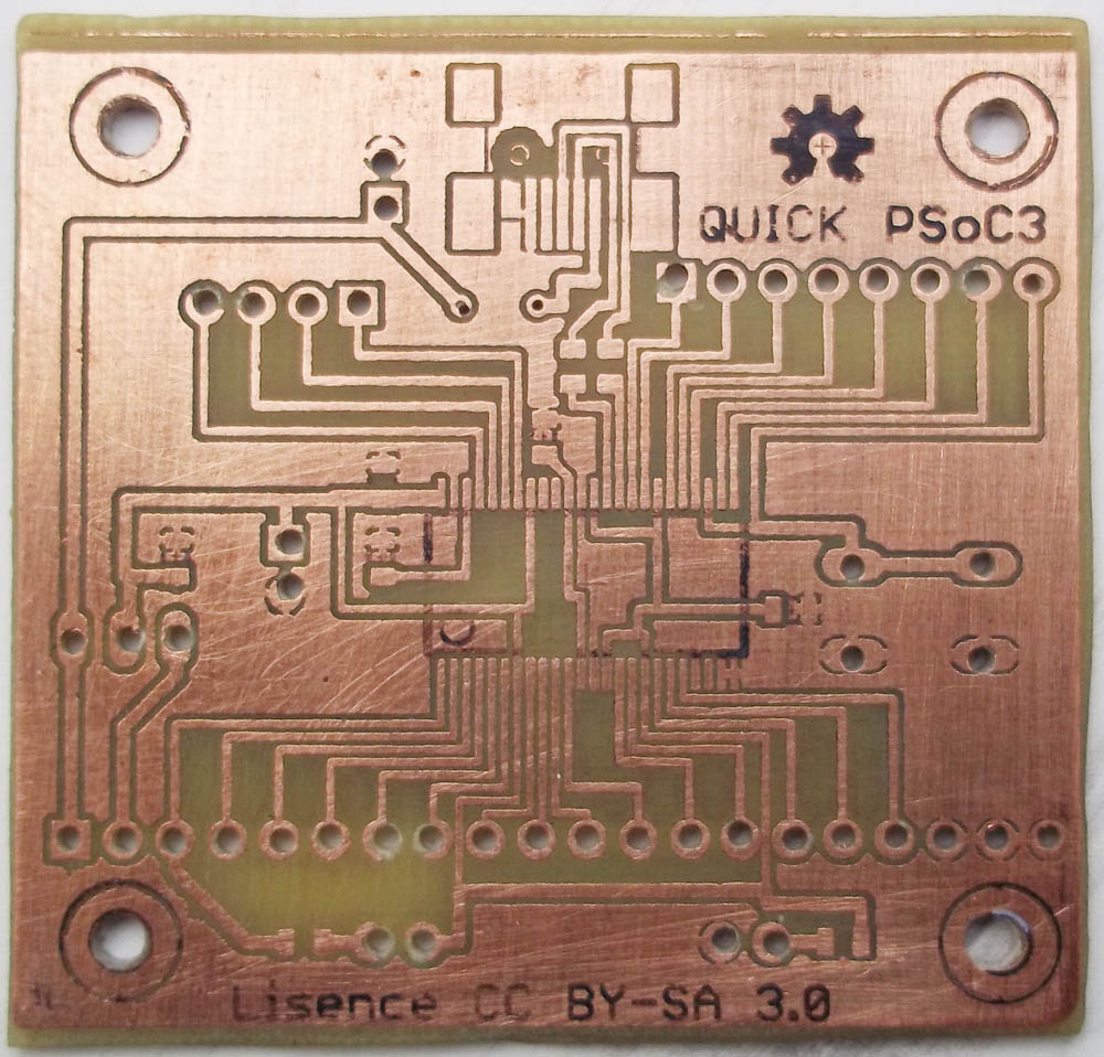
Following my last post on a simplified PSoC3 board,a friend of mine re-designed it,and sent it over for testing.
Here are some pictures,linked over from his account on fabricating this:
and in its coppery glory,
(I don't have access to a camera,so you'll have to put up with my wacky narration.)

It was now my turn to add the chip and program this one.I had some issues with VCC-GND shorts(yeah,theyre the worst) beneath the chip(no soldermask,eh?),so I had to desolder the chip once and then do it again.Now,desoldering this seemed like a near impossible task,but I used this method here(Youtube Video Link) and though it looked impossible to me,it worked just as easily as the video shows!..

So a after a few tense minutes,and the 'Aha!' moment of eliminating the short,and then getting the chip back where it belonged,I found I had a short again.Examining the tracks revealed that the initial short had burnt up a small bit from each of the VDDD and GND pins and they were sitting in a black pool of flux.Since I didn't have any solvent with me,I tried flooding the pins with solder and then wiping that area clean with some solder wick.The mess was cleaned up,to reveal a small bit of track missing from each of the VDDD and GND pins.So I lifted those up with tweezers and re-wired them manually to their correct locations.

With that done,though it looked ugly,it behaved beautifully.The MiniProg3 picked it up easily,and I was successfully able to program the bootloader in,and then a simple LED blinking bootloadable,with surprising ease.I must say,this USB bootloading stuff(Appnote link) is pretty neat!

So the point is,a single sided,easy to use PSoC3 board with USB Bootloading? No sweat.

I'll clean up the files and upload them soon.The files(PCB files made in EAGLE V5.8.0 and Bootloader Project,made in PSoC Creator 2.0) are linked here,from my 4shared account.

Heres what it looks like after those few crazy hours:


Feel free to send in suggestions,criticism,feedback via the comments.

 This work is licensed under a Creative Commons Attribution-ShareAlike 3.0 Unported License.

Sunday, January 8, 2012

PSoC3 Hardware - Quick and Dirty

(Part 2 of this post,PSoC3 Hardware - Quick and Dirty - Fab & Testing. )

One boring sunday morning,I decide to throw together no frills,basic PSoC3 hardware,that could be truly home manufactured,unlike my last attempt.Done in under 2 hours with some bad shortcuts,I decided to call this a Quick and Dirty version.I think this should be do-able with the traditional toner transfer method on a double sided copper clad board.


A few notes on the design:
-P15[0] and [1] have not been routed out.
-Currently,the chip pads are just long enough (and maybe shorter than they need to be for those new to SMD work),so you might need to bend the pins on the chip inwards and then solder,for an easier fit.
-There is no protection on the USB power lines,so beware.
-There is no reverse polarity protection over the unregulated input "VIN".
-There is no dedicated programming header for the MiniProg3,so that something that you've to connect with _short_ single wire connectors.(short because those lines will be in high frequency data lines,min. 1.5Mhz.)

A few notes on fabrication:
-The LEDs need to soldered on both ends,so they shouldn't be inserted fully flush with the board surface.
-The 2 10uF capacitors need not be soldered on both ends,since a connected via is provided for each,which will need to be done.
-There are no vias beneath the chip,and only 2 vias are position critical.
-There are no components on the bottom layer.
-Feel free to increase the via diameter,I've kept it to eagle's defaults.
-Dont make those holes beneath the miniUSB connector.I couldnt find a MiniUSB connector without those holes in a reliable and marked pinout,so I've left it that way.
 
The design files are made in EAGLE V5.8.0 and you may find them in my 4shared account,I'll upload them soon.

Any mistakes,suggestions,criticism or your experiences making this or similar hardware are most welcome in the comments :-)

This work is licensed under a Creative Commons Attribution-ShareAlike 3.0 Unported License.

Saturday, January 7, 2012

MiniProg3 + EzI2C + ADC = Crude O'Scope

I'm documenting something here that I did recently,which was setting up a crude oscilloscope( real-time waveform viewer could be a better term ).While such data acquisition systems aren't difficult to put together,especially with the PSoC3,but I wanted something quick,so this is what I threw together.

I utilized the USB<->I2C bridge functionality of the MiniProg3,and used the Bridge Control Panel that comes with PSoC Programmer to view the ADC data sent over I2C in realtime,to the PC via the MiniProg.So yes,its quite simple and took me under 20mins to get going.

 I'd like to talk about EzI2C Component,since I find it to be truly "Ez" to use and also a great idea.In short,This component adds an I2C slave device with one or two I2C addresses. Either address may access a memory buffer defined in RAM, EEPROM, or flash data space. EEPROM and flash
memory buffers are read only, while RAM buffers may be read/write.This memory is therefore "common" to both PSoC and other devices on the I2C bus,so its really good and easy for implementing control and status as well as data transfer,since all the I2C stuff is taken care of below the high level APIs,leaving you to focus on things better.

You can check out the video in the link below,and its example project included with Creator 2.0

Video : EzI2C Slave Component in PSoC 3 and PSoC 5

Below is a screenshot of the Bridge Control Panel showing the waveform:
Just incase youre wondering,the blue line is a "flag" I set at 50% of the max value,in the Bridge Control Panel GUI.

This code was tested on the CY8CKIT-030,and was written in PSoC Creator 2.0 and Bridge Control Panel 1.3.

Heres what the top design view looks like:

You can find the code and Bridge Control Panel Command and Settings files in my 4shared account,linked here.

I havent gone into details on how to use the Bridge Control Panel,since I found the included help files are good enough.However,if you want a clarification at any point,drop a line in the comments.

This work is licensed under a Creative Commons Attribution-ShareAlike 3.0 Unported License.

Saturday, December 31, 2011

PSoC3 Custom Board - Soldering the chip

For any first timers that stumbled onto this post,the chip here refers to a 48 pin SSOP package with a 0.635mm(25mils) pin pitch.

Things didnt go that well on the first board I tried out,mainly due to me using the wrong type of tip.After this,I was able to use sharper tip (from my brother,all credits to him.),which did the trick and I was able to do chips with little effort.The equipment and sequence of events that worked for me,in order are as below.The method I describe below is inspired from this post by Arup Basak of CircuitsDIY ,so credits to him :-).

Equipment Used:
1.Any cheaply available 1mm solder wire,(don't recall the price,bought this last year)
2.Liquid Flux,I used a locally available liquid flux,its a pinkish liquid in an unmarked dropper bottle.
(A 30ml bottle cost me Rs.10)
3.A chisel tip and a sharp pin like tip for your iron,(Soldron tips cost me around Rs.40 per tip,a few months ago.)
4.The soldering iron itself.Many claim that cheap 25-30W irons that connect directly to your AC mains supply wouldn't be used for SMD work,but that is all I had around,so that is what I used.It is a 25W one from Soldron,the most common one you'll see in India.
5.Solder wick(Rs.10 for a 1m roll)
6.Patience,which is extremely critical for this number of pins and fine pitch we are working with here.

Instructions:

1.Flux the pads.

2.Use a chisel tipped soldering iron and 'relay' solder onto it.What I mean is,no applying solder directly to the pads,rather melt some solder onto the tip and then lightly pass the thick(relatively) tip lightly over 5-8 pins,applying solder this way.The ideal height would be where only the solder blob grazes the pins,getting consumed while you pass it over the pins.

3.After you're done adding solder to the pads this way,align the chip and use some means to hold it in place while you solder the pins.Many people use Kapton Tape,or let the viscous flux do that,but I just held it down with my index and forefinger.

4.While you make sure its aligned,come in with a sharp tipped iron and solder the 4 corner pins,in the order of top left,top right,bottom left and finally bottom right.When I write solder,I mean, NO SOLDER on the tip.Clean your tip and just touch the pins to melt the solder on the pads into a nice union of pin and pad.DO NOT keep your iron there for more than 2 seconds,or come in for consecutive 'tacks' on the same pin,doubting the joint or just wanting to make it look shinier(the pad(s) will overheat,and you will cause it to come off),you could wreck your PCB.Solder each of the 48 pins this way.

5.After you've patiently done one row of 24 pins,flip it around,do the other row and then test the pins' joints by prodding them individually with sharp forceps(I use the kind used for dissection of lab animals).

In case you get solder bridges between pins (which you wont,if you follow the no-solder-on-tip-while-tacking-pins very strictly) use the solder-wick,but don't keep your iron there for more than a second or two,since the tracks there will be fine,and can come off.That is how I made those 2 mistakes earlier.

Here are some pics of my end result:


I have currently populated all the parts I have,so progress will pause on this till I get more parts from local dealers+KitsNSpares.

PSoC3 Custom Board - What next?

While development on this is underway,I've been thinking of the future of this project.
The initial goal I set out with,was to provide easy access to the PSoC3 platform to students and hobbyists,at a low price.
Though this sounds good,I'm not so sure now.There are a number of issues to do with the design(?),fabrication and parts sourcing that I'm concerned about.

The Design:
-I've missed 1uF storage caps at 2 places,but I'm hoping that isnt a deal breaker.
-Theres going to be a change in the USB connector,towards a miniusb type instead of the current one..(for sure in the future revisions)
-I guess this list shall extend as I test this further..

Fabrication:
-The current deal I have is just too costly.The way ahead on this front would mostly be engaging the services of either SeeedStudio's Fusion Service or ITead's OpenPCB,both giving me 10 5cmX5cm boards for a total of around USD 14(incl. shipping),excluding the import duty I might have to pay.
-Theres another option here,the SeeedStudio Propagate service,which is board fabrication+assembly,with a minimum order of 100 boards.

Parts Sourcing:
-Currently,I'm using chips I got as free samples from Cypress.The price listed on the chip's page is almost USD 20,with an MOQ of 60,which screws up everything to do with "low cost".
-Other parts(SMD passives mainly)can be taken care of by ordering in larger quantities (MOQ is 100 on most smd parts at locally),and again not a problem if I'm using the Propagate service.

Now the real question and answer to the above doubts and concerns is,"Does anyone even want to buy this?".Since,if there is a market out there for these,then things move to a different scale and the above issues can be resolved.
If not,then the project ends as a very enriching academic pursuit.